FEA & industrial simulation • Michigan

Validate the design.
Before you build.

One component. One cell. A defined engineering study.

Can the tooling handle the load? Can the cell meet the target cycle? Explore FEA, robot simulation and engineering studies for tooling, production performance and controls readiness.

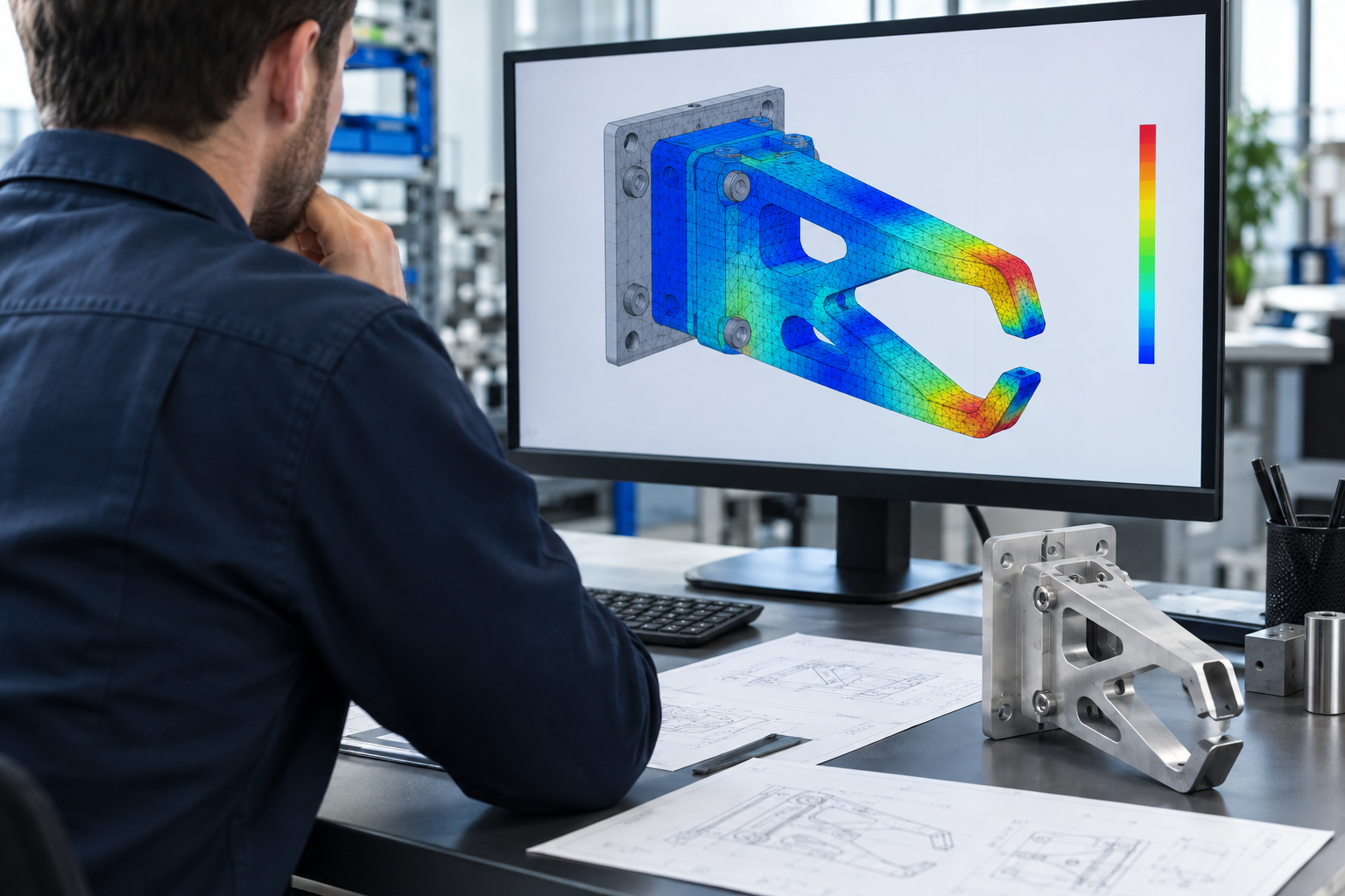
Illustrative engineering workstation showing a finite element model of robot tooling
SOLIDWORKS FEATooling & machine components
Robot simulationReach, clearances & layout
Cycle time studiesSequence & component capability
Payload & inertiaGrippers & robot tooling

Selected client projects

Engineering experience.
Specific applications.

Explore FEA work for KUKA and completed simulation studies for Reinhart Industries and EPIC, with defined scopes and documented engineering outputs.

Reinhart IndustriesRobot simulation

Robot reach and layout verification.

Evaluating robot positions, working clearances and access against the updated layout of an automated cell.

Project package
Reach study report + verified layout

Read the project story
EPICFEA + robot feasibility

Structural dynamics.
Robot feasibility.

Two distinct studies: modal analysis of an NVH assembly, and robot access and manipulation around an assembly fixture.

Project packages
Modal analysis report + feasibility study

Read the project story

Project summaries prepared by Spinula from completed engineering records.

Choose the question to answer

Verify the load.
Check the cycle.

Each study has its own inputs and acceptance criteria. We agree on the scope before analysis begins, so the deliverable answers the question behind your project.

01

Structural FEA

Evaluate robot grippers, fixtures, pallets and machine components under defined loading conditions.

  • Stress and displacement
  • Factor-of-safety evaluation
  • Material, mounting and load assumptions
Explore this service
02

Cycle time studies

Evaluate whether the proposed sequence and selected components can support the required cycle time.

  • Robot motion, tooling actuation and process dwell
  • Component timing against available technical data
  • Limiting operations and improvement options
03

Payload & inertia studies

Check the complete end-of-arm tooling and handled part against the selected robot’s loading limits.

  • Combined mass and center of gravity
  • Moments of inertia and load configurations
  • Robot compatibility and tooling design implications
Explore this service
04

Robot reach & layout

Evaluate access and clearances before committing to equipment positions.

  • Reach and interference review
  • Robot positions, orientations and heights
  • Verified layout and study findings
05

Modal analysis

Understand the natural frequencies and mode shapes of an assembly.

  • Finite element model preparation
  • Frequency and mode-shape extraction
  • Technical report and engineering interpretation
06

Automation simulation

Use Emulate3D to investigate the operation of a proposed automation concept.

  • Cell behavior and sequence visualization
  • Comparison of agreed operating scenarios
  • Model scope and outputs defined with your team

Production & advanced engineering studies

Plan production.
Refine the design.

Test controls with Emulate3D virtual commissioning, or explore capacity, programming and advanced analysis studies. We define the model, required data and deliverables with your team before work begins.

07

Virtual commissioning with Emulate3D

Test PLC/HMI logic and operating sequences against an Emulate3D model before physical installation. Include virtual FAT scenarios in the agreed scope.

  • I/O behavior, sequences and interlocks
  • Fault, stop and restart scenarios
  • Agreed test plan and findings report
Explore this service
08

Throughput & bottleneck studies

Explore whether the complete line can support the required output across operating scenarios.

  • Parts per hour, product mix and availability
  • Buffers, waiting and blocked operations
  • Layout and capacity scenario comparison
09

Tooling weight & stiffness optimization

Compare tooling designs to reduce mass and inertia while meeting defined structural requirements.

  • Geometry and material alternatives
  • Strength, stiffness and robot load implications
  • Comparison report and scoped design revisions
10

Offline robot programming

Discuss preparing robot programs in a virtual cell to support subsequent integration.

  • Robot, controller and software compatibility
  • Paths, sequence and interference review
  • Program handoff with calibration requirements
11

Fatigue & durability studies

Investigate the effect of repeated loading on tooling and machine components.

  • Load histories and duty cycles
  • Material fatigue data and analysis assumptions
  • Life estimates and design implications
12

Advanced dynamic analysis

Discuss how changing loads or excitation affect an assembly over time.

  • Harmonic or transient response, as applicable
  • Excitation, damping and boundary conditions
  • Response evaluation against agreed limits

One project. A coordinated scope.

Combine the studies relevant to your decision, with defined inputs and acceptance criteria for each. Virtual testing, physical validation and on-site commissioning are scoped separately.

Discuss your study scope →

Cycle time & component selection

Will the selected equipment
meet your production target?

A reachable position is only part of the answer. We study the sequence, motion and process times needed to complete the cycle.

Discuss your target cycle →
01

Define the target

Required seconds per cycle, parts per cycle, product variants and operating sequence.

02

Check the components

Review robot moves, grippers, actuators, transfers and process equipment included in the scope against their specified capabilities.

03

Identify what limits the cycle

Document estimated timings, synchronization constraints and options to review before hardware selection.

Estimates depend on model fidelity, motion settings and supplier data. Physical performance is verified during testing and commissioning.

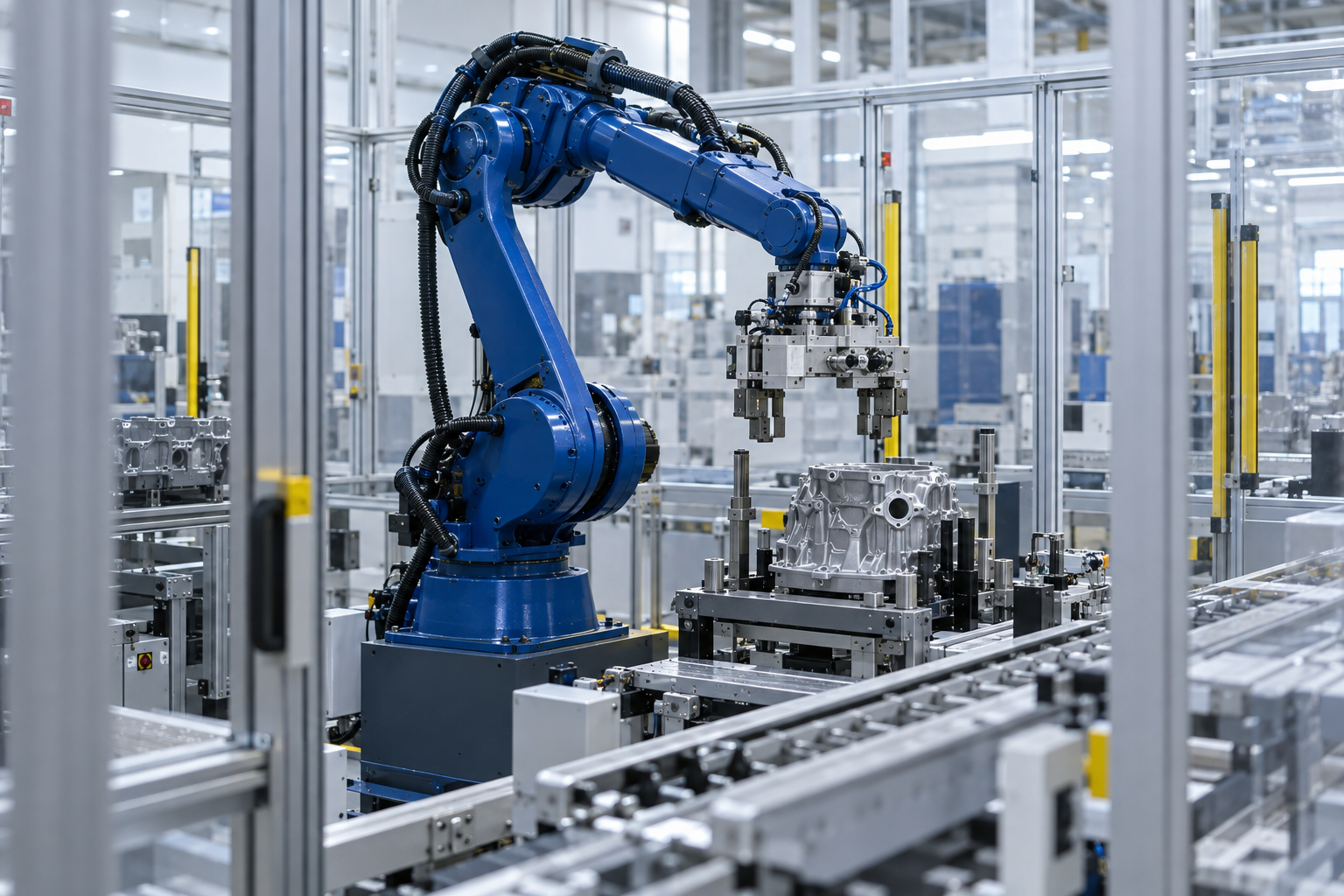
Illustrative robotic manufacturing cell with tooling, fixture and guarded conveyor

More than a simulation image

Give your team a basis
for the next decision.

Start with an existing design or combine the study with gripper development and mechanical documentation.

  1. 01
    Agreed analysis basis

    Input models, materials, loads, constraints and acceptance criteria relevant to the study.

  2. 02
    Engineering findings

    Results, limitations and design implications in a technical report.

  3. 03
    Application-specific outputs

    Cycle and capacity comparisons, payload assessments, virtual test findings, analysis reports, robot program packages or design documentation, according to the agreed study scope.

A practical first engagement

Start with one study.
Build on clear findings.

01 / Define

Share the engineering question

Tell us what must be verified. We review CAD availability, operating conditions, requirements and timing.

02 / Analyze

Establish the model and scope

Agree on assumptions and deliverables, then evaluate the design against the defined study criteria.

03 / Review

Put the findings to work

Review the results and next design decisions with our team. Revisions and additional variants are defined in the proposal.

Before you send your model

Project questions

What information do you need for a quote?

A project summary, CAD availability, materials, loads, mounting conditions, acceptance criteria and target date. For robot studies, include the robot model, tooling and part data, and cell layout. For cycle and capacity studies, add the production target, operating sequence, product mix and component specifications. Controls studies need the PLC/HMI platform and program availability; fatigue and dynamic studies need load histories, duty cycles and material data. We can agree on the file exchange process after the initial review.

Which FEA software do you use?

We use SOLIDWORKS for structural FEA. For fatigue and advanced dynamics, the analysis method, software requirements and suitability are confirmed during technical scoping.

Is payload verification just a weight check?

No. Tooling and part mass, center of gravity and moments of inertia affect compatibility with the selected robot. We define the loading configurations and compare them with the available manufacturer limits.

Can you combine the studies for one robotic cell?

Yes. Structural FEA, payload and inertia, reach and cycle time can be quoted as a coordinated package. Additional production, controls, optimization or advanced analysis studies can be included after technical review. Each study keeps its own inputs, assumptions and acceptance criteria.

Can you include gripper design and drawings?

Yes. Gripper concept, 3D modeling, 2D detailing and BOM preparation can be quoted together with the validation studies.

Do you also work with Emulate3D?

Yes. We use Emulate3D for automation simulation and virtual commissioning, connecting a virtual machine or cell model to the controls being tested. We agree on controller compatibility, model detail and test scenarios with your team.

How is throughput different from cycle time?

A cycle study evaluates the timing of a defined operation or sequence. A throughput study considers the wider production system, including product mix, availability, buffers and interactions between stations.

What is included in virtual commissioning?

We use Emulate3D to test control logic and sequences against a virtual machine or cell model. The scope defines controller connections, I/O behavior, operating modes, fault and recovery scenarios, and the test findings to deliver. Physical acceptance testing and commissioning remain separate activities.

Can offline programs run directly on the real robot?

Programs must match the agreed robot and controller configuration. Calibration, tool and frame verification, commissioning and final validation on the physical cell are defined separately.

Are physical testing and commissioning included?

The analysis package covers the engineering study described in the proposal. Physical testing, on-site robot programming, installation and commissioning must be discussed and scoped separately. Offline programming is available for consultation as a defined study package.

Start with one defined study

What does your design
need to prove?

Tell us about the component or cell, the decision you need to make and your target date. We will define the inputs and scope with your team.

Spinula Engineering

+1 (517) 262-2149

1226 E McDevitt Ave
Jackson, MI 49203

Engineering support for Midwest machine builders and automation integrators.