Robotics
Robot payload vs. inertia: what to check before selecting a robot
Why tooling mass alone is not enough, how the center of gravity and inertia change the assessment, and what to include in your load data.
Check the complete carried load, its center of gravity and its moments of inertia using the selected robot’s manufacturer data. A nominal payload rating alone does not demonstrate compatibility or cycle time.
Three properties describe different parts of the problem
The workpiece may be the part that production needs to move, but the robot also carries the gripper and other attached equipment. Start by defining that complete configuration, then distinguish its mass from how that mass is distributed.
| Property | Question it answers | Information to preserve |
|---|---|---|
| Mass | How much does the defined configuration contain? | Included components, units and material assignments |
| Center of gravity | Where is the combined mass located? | Coordinates and reference frame |
| Moments of inertia | How is the mass distributed relative to the specified axes? | Axes, units and the point about which values are reported |
KUKA’s load evaluation guidance explicitly includes mass, center of mass and inertia, with static and dynamic load evaluation. This is a useful example of why a complete robot load assessment goes beyond one weight value. The correct method and limits still depend on the particular robot. See KUKA Load.
Build an inventory of what the robot carries
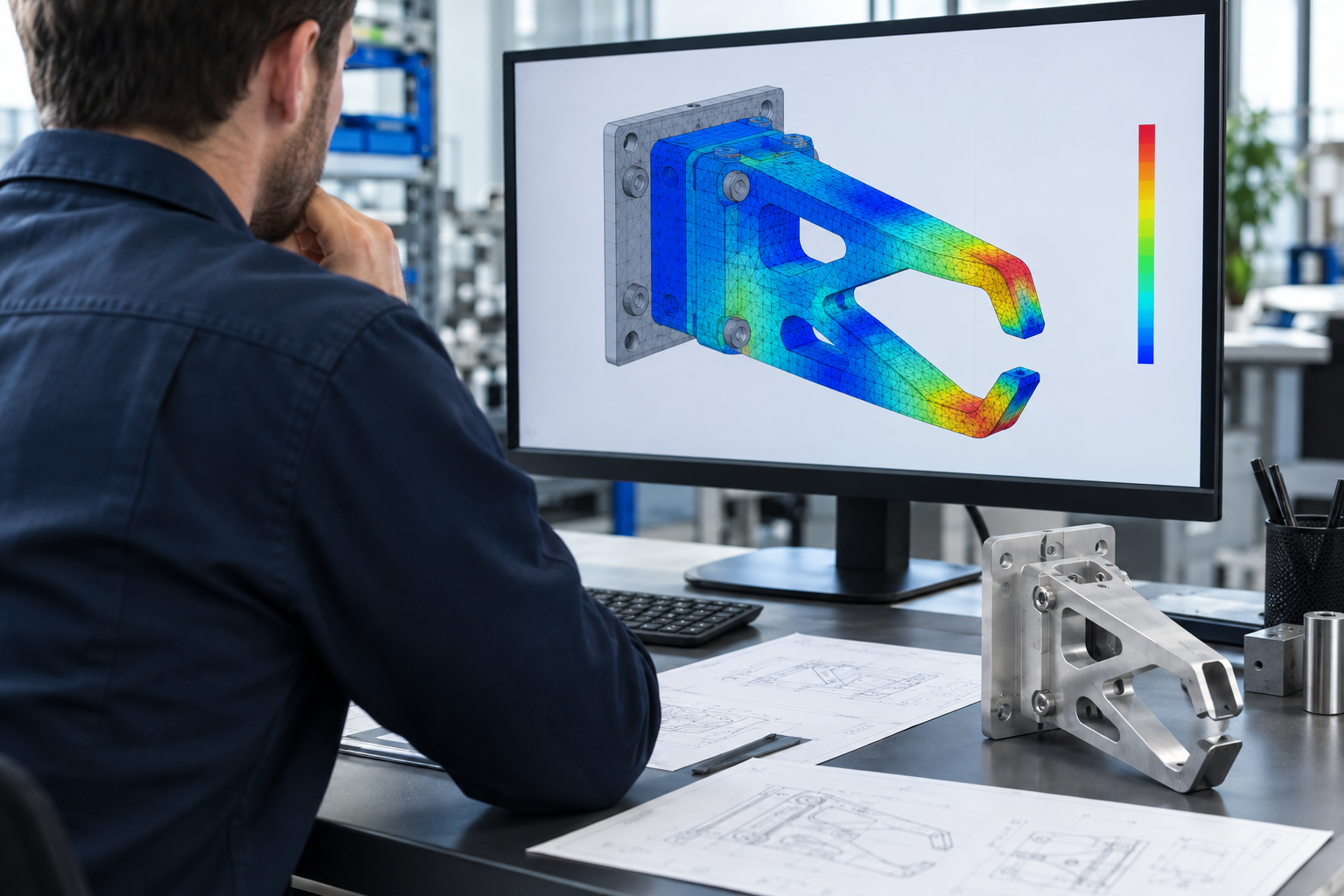
Review the gripper body, fingers, mounting adapters, tool changer where applicable, sensors and other carried equipment. Add the handled part for each relevant operating configuration. Check whether CAD mass properties include purchased components correctly rather than treating every solid as the same material.
Keep the source of each mass value traceable. A supplier specification, a weighed assembly and a CAD estimate have different origins; documenting the source makes discrepancies easier to investigate. Also identify cable, hose or other external loading effects that may need separate consideration.
Why the same mass can produce a different assessment
Consider two versions of a gripper with the same total mass. One places a component close to the mounting interface; the other moves it farther away on an extension. The total mass is unchanged, but the center of gravity and inertia can change. The robot compatibility assessment therefore needs updated load data.
This is also why removing material from a convenient location does not necessarily address the controlling requirement. Before revising the tool, identify which property or operating condition is limiting the application, then compare alternatives using consistent configurations.
Keep coordinate systems and units explicit
A mass-properties export is only useful if the recipient knows how to interpret it. State the reference origin and axis directions. Confirm whether the required inertia values are about the center of mass or another reference point, and provide the format required by the manufacturer’s evaluation method.
Do not copy values between software tools without checking conventions and units. Ask for a sketch showing the frame if the model orientation is ambiguous. A small amount of documentation here can prevent a fundamentally different load from being entered into the evaluation.
Evaluate the configurations that actually occur
List the part variants and relevant tooling positions. Loaded and unloaded conditions are not the only possible states: a gripper may change geometry, carry more than one item or pick parts at different locations. Define which combinations the study covers and which are excluded.
The exact robot model matters. Use applicable manufacturer documentation and evaluation tools, and identify missing operating information before drawing a conclusion. A study of one configuration should not silently become approval for every future tooling revision.
Keep payload, strength and cycle time connected
A compatible load does not demonstrate that the tooling is sufficiently stiff, that every position is reachable or that the required cycle time is achievable. Those decisions need structural, layout or motion information respectively. Coordinate the inputs across the studies, but retain a clear acceptance question for each.
For a first request, send the robot model, complete tooling CAD, mass information, part variants and target operating sequence. State whether the decision is robot selection, a tooling change or investigation of an existing application. That context helps define a useful payload and inertia study.
Apply this to your project
Turn your question into a defined study.
Tell us about the application, available data and the decision you need to make.